
The intense pulsed positron source (IPPS)
The goal of the intense pulsed positron source is the development of a device for the accumulation and storage of large amounts of positrons (~10^12 e^+), at low positron energies (<1 eV) and for long times (>1 h).
APEX:
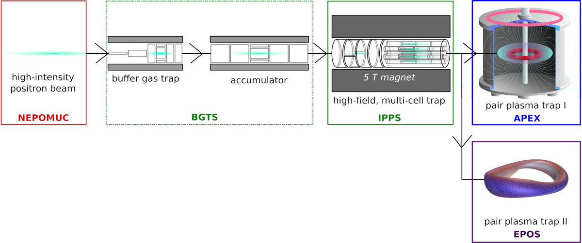
The project (IPPS) is part of the APEX (A Positron Electron EXperiment) collaboration which pursues the formation of the first large scale, low Debye-length electron-positron plasma (AIP 1668, 040004 (2015)). The overall scheme is shown in Figure 1.
The high intense beam of the neutron-induced positron source Munich (NEPOMUC) will be guided into a buffer-gas trap and accumulator (AIP 1521, 101 (2013)). There, the positrons are decelerated by buffer-gas collisions with N_2 and cooled by a cooling gas (SF_6 or CF_4) and afterwards stacked in the accumulator forpulses of up to 10^9 positrons. Then the positrons are guided into the high-field multi-cell trap which further accumulates the positron pulses until a total charge of up to 10^12 e^+ is reached. The actual pair-plasma experiments take place within the trap. Its main component is a levitating super conducting coil, which creates a confining magnetic field for both electrons and positrons (APEX). In a parallel approach a tabletop stellarator (EPOS – electrons and positrons in an optimized stellerator) will be developed which addressess complement questions of a pair plasmas.
IPPS:
For the IPPS – and also the buffer gas traps – so called Penning-Malmberg traps are utilized. In a Penning-Malmberg trap the plasma (made of constituents of one sign of charge) is trapped radially by a (homogeneous) magnetic field and axially by an electrical field. To confine the pursued charge of 10^12 e^+ unacceptable high electrical potentials are necessary, which in addition, can lead to a heating of the plasma.
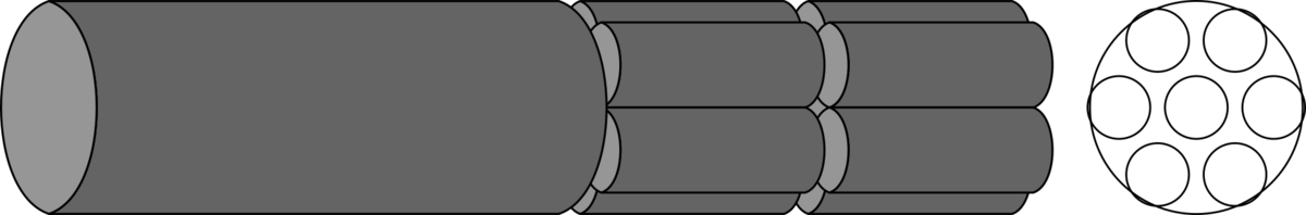
Therefore, the idea of a multi-cell Penning-Malmberg trap is pursued (Radiat. Phys. Chem. 68, 419 (2003)). In such a trap the charge is separated radially in small amounts and the necessary usage of high electric potentials is circumvented by use of parallel traps. A general scheme for the planned multi-cell trap is shown in Figure. 2.
The left trap will capture and accumulate positrons arriving from the BGT until a threshold number of charge isreached. Afterwards the trapped plasma is excited radially and injected into one of the smaller traps. This procedure is repeated until all cells are filled and an overall charge of up to 10^12 e^+ is stored.
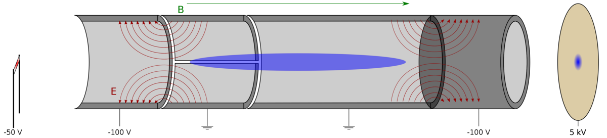
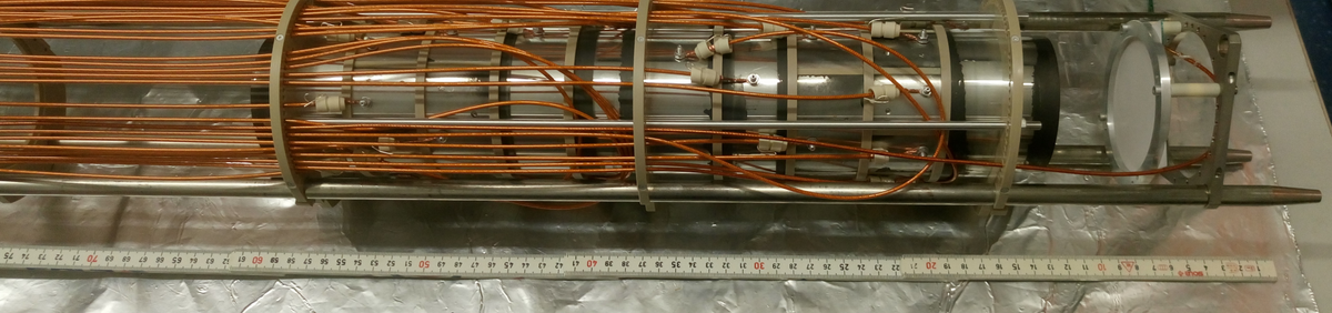
The current experimental scheme is shown in Fig. 3 and a photo in Fig. 4. At the moment the experiment runs with electrons instead of positrons because large amounts of electrons can be produced much easier (and cheaper). The electron emitter is a hot cathode. Once the trap is filled different schemes are tested and optimized to develop all necessary techniques to investigate the plasma state and fill the multi cells.
In the next step the trap will be modified and a few multi-cell traps will be installed. With these traps the first-time multiple plasmas in different off-axis storage cells will be trapped. A couple of questions will be addressed which have to be answered on the way to a full functioning multi-cell trap. For example, at the moment it is not decided how the ejection of the charge is going to happen. The plasma could either be ejected in one big pulse or by emptying the cells one after the other. Also, questions concerning the storage of high plasma space charge, their radial expansion and the application of radial compression through rotating electrical fields will be addressed.