Documentation / Guided Example of the 3D Particle Tracking Toolbox for MATLAB®
General Instructions
The usual entry points to this toolbox are the "do_*.m"-scripts in its main path. These should be opened with an editor and a copy of these scripts should be placed in each "measurement"-folder. Firstly, edit the parameters in the script. Afterwards, run section-by-section of the script from the matlab editor.
Note: The "settings"-structure is used as a parameter by many functions. If you use only a single part of the toolbox, consider possible errors as a missing information in the settings-structure (e.g. path information). Also, have a look in the earlier entry scripts, if some field in the settings file is missing.
UPDATE: To run the "Shake-the-box"-type example, go into the "EXAMPLE_STB" folder and run the do_EXAMPLE.m - skript.
Camera Calibration
CALL:
imageLocations = locateCalibImages;
settings = autoCalibSettings_GUI(imageLocations);
...then save the settings-file to disk (i.e. cameraX.mat) ...
!! Repeat for each camera.
cameraSystem = calibrateFromTarget();
This will ask for the N files you saved to disk.
Taking target images:
You can find the target pattern in the calibration folder of the toolbox in the *.ai, *.eps and *.ps format. The cameras must capture the target image synchronously, but the target image does not need to be visible in all cameras at the same time. Usually it is sufficient to record about 5 images for each pair of cameras looking at the target. For three cameras this makes >15 images. More images give better statistics.
A dot pattern is far more accurate than a checkerboard-pattern especially when unsharp images are captured since the centroid of a blurred marker dot is still very accurately determined.
Process the target images:
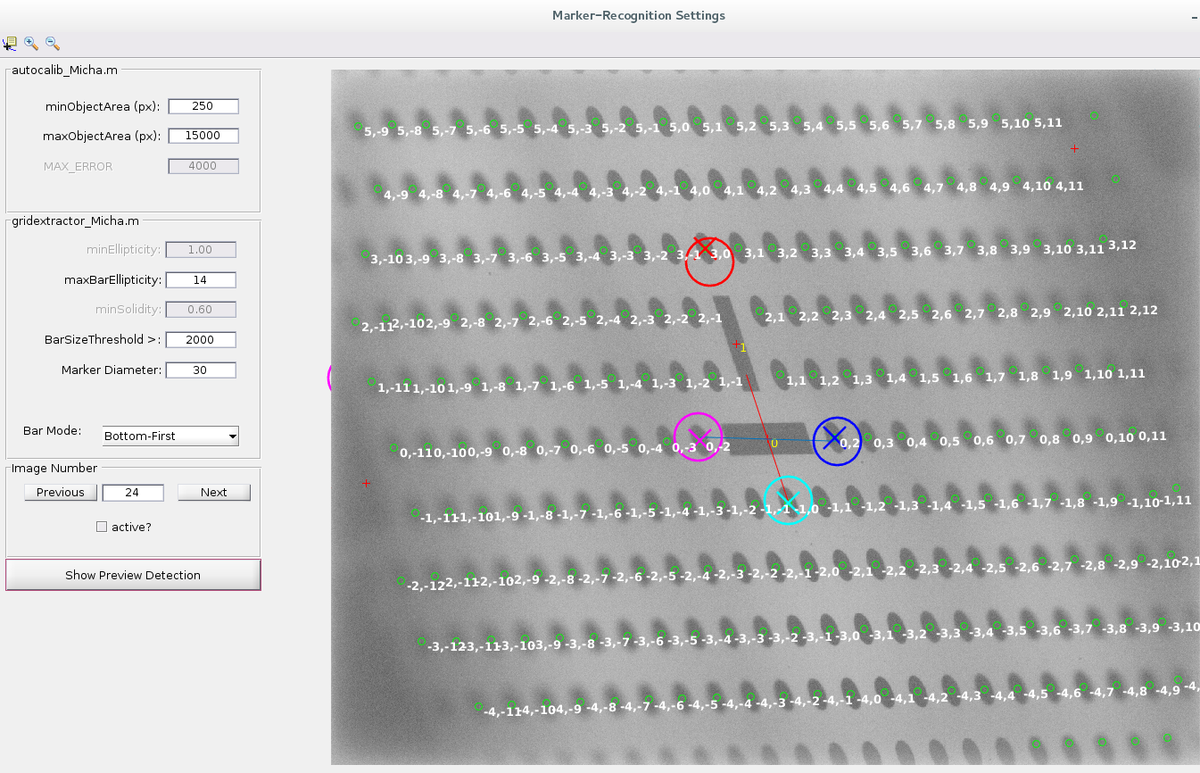
In the image on the right, the image processing GUI is shown. The most important settings are:
- MinObjectArea (place a value < the size of your target dots)
- BarSizeThreshold (objects larger than this will be considered as a "bar" (red cross) and not as a "marker" (green circle)
- Bar Mode (helps the GUI to find the correct positioning of the two bars)
After a successfull "Show Preview Detection", check the "active"-checkbox and continue to the "Next" frame. When the target cannot be analyzed in a certain image, uncheck the "active"-checkbox. When you are done with all images, simply close the GUI and be sure to save the results!
To reduce numeric errors in later stages, the cameraSystem variable should be aligned in such a way that the world coordinate origin lies within the reconstruction volume. From the calibration algorithm, by default, camera 1 is the coordinate origin and all other cameras are located accordingly with respect to camera . To move the world coordinate origin to the reconstruction volume , two methods are available presently, namely cameraSystem.alignSystemPFC and alignSystemRectangular. Have a look into the routines to align the system in your own manner (and mail me the code so that I can include it).
2D-Particle Position Detection
CALL:
settings.cam1_filename = './particleImages/rot/rot%05d.bmp';
settings.cam2_filename = './particleImages/gelb/gelb%05d.bmp';
settings.cam3_filename = './particleImages/gruen/gruen%05d.bmp';
settings.output2Dcoords = './coords/coords2d_%05d.dat';
settings.im_range = 1:10;
settings = image_file_check(settings);
The following collects the appropriate settings:
settings = particle_detection_GUI(settings,1);
settings = particle_detection_GUI(settings,2);
settings = particle_detection_GUI(settings,3);
Start the actual detection
do_detection_2D(settings, 1); % the second argument triggers an graphical output
Details:
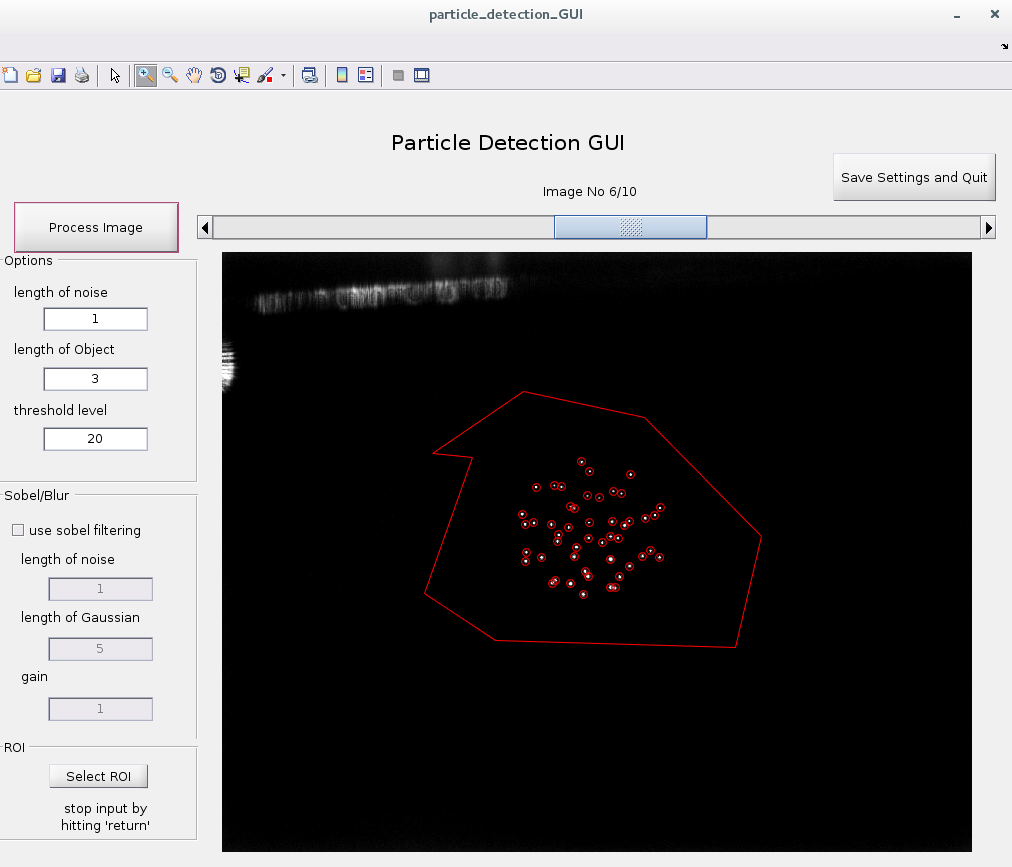
The 2D-detection uses a Gaussian bandpass filter to detect the particles while suppressing noise. The optional Sobel-filter is applied before the particle detection. It is very useful to detect the locations of unsharp particles. Just figure out what is suitable for your application.
HINT:
To test the results for pixel-locking use the "showSubpixelMap(settings, frameNumber)"-function.
Disparity-based Calibration Refinement
CALL:
do_disparityRefinement.m
This contains all necessary parameters and includes an iterative refinement of the epipolar line distance. Open it in the editor and have a look at the parameters.
Details:
Usually, even if you take special care, there will be slight deviations between the calibration state and the measurement state of the camera system. In our case, the deviations of ~1-4px have been observed which have been identified to be pure translational effects. The focal length and other camera parameters remained very constant during the measurements. Thus, this calibration refinement procedure allows each camera to be translated (not rotated) along its sensor-plane. For the sake of reproducibility, this is done by altering the principal point (u0,v0) of the intrinsic camera parameters.
Procedure:
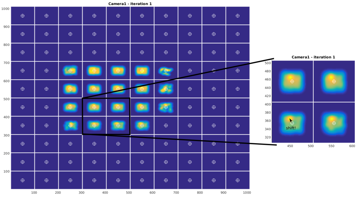
A correspondence analysis with very large epipolar-line distance is performed (e.g. when the expected deviation from the epipolar line is about 5 px, the allowed epipolar distance is set to more than 10 px) . This creates many erroneous 3D-points, but also the fewer correct correspondences. All these points are back-projected onto each camera. The disparity between the reprojected 2D-point and the initial 2D point from particle detection can then be used to find the translational (2D) shift of the camera:
All disparities are computed and sorted into binned regions of the image by its 2D-image position. Each disparity-vector is then represented by a Gaussian blob in a virtual "disparity-map". All of these blobs for each reprojected point are then summed up to create a final disparity map for each camera. The possible shift of the camera is then indicated by a deviation of the disparity map intensity from the cell center.
Sometimes, there is no good statistic in some regions of the images, so the user decides what "cells" of the disparity map should be considered for the detection of the camera shift.
Correspondence Analysis
CALL:
settings.params_3CAM3D.epipolar_distance = 0.9;
settings.output3Dcoords = './coords3d/output3d_%05d.dat';
threeCam3D_alg(settings, cameraSystem, 1);
- cameraSystem as returned from the calibration routine
- last input triggers plot number vs. frame
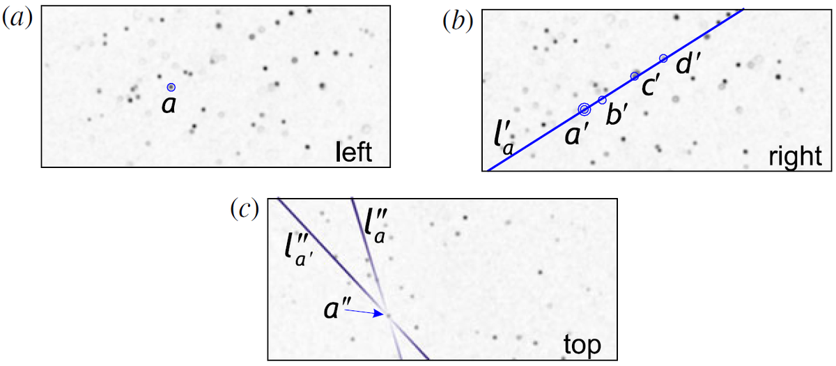
The correspondence analysis looks for particle correspondences in three cameras. The following will be done for all permutations of the camera numbers (123, 231, 312,...):
- select particle a in camera 1
- project epipolar line l'a to camera 2
- find candidates that lie in the "epipolar-distance" to this line in camera 2
- project the lines l'a and l''a to camera 3 (from camera 1 and camera 2)
- if a particles is located near (again, the epipolar-distace is used) the intersection of l'a and l''a, the correspondence is confirmed.
The results of the correspondence analysis will be stored in the folder:
(settings.output3dCoords)/cam123/coords3d_%05d.dat
(settings.output3dCoords)/cam132/coords3d_%05d.dat
(settings.output3dCoords)/cam213/coords3d_%05d.dat
...
NOTE: There is a function called "refineCalibration.m" to check the correspondences manually. Simply call refineCalibration(settings) after the 2D-detection and with all necessary paths given.
Multiset Triangulation
CALL:
frameToProcess = 1600:3000;
visInNumofPerms = 5;
clusterSizeApprox = 0.05;
doShow = 0;
writeToDisk = 1;
triangulationToCluster(settings, frameToProcess, visInNumofPerms, clusterSizeApprox, doShow, writeToDisk);
Details:
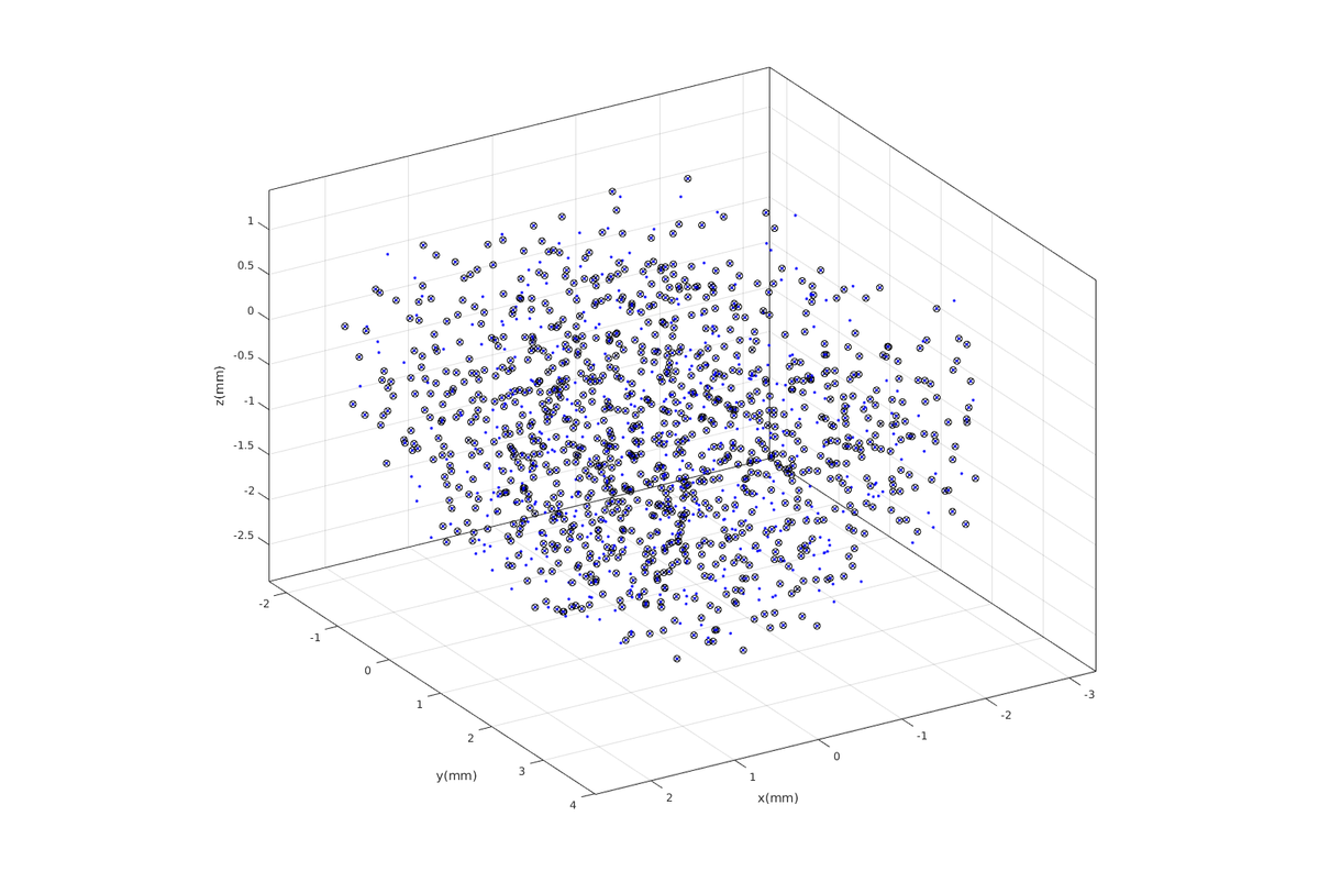
The above described correspondence analysis has been carried out with all permutations of the available cameras. This means, there are 6 sets of 3D particle positions from the three cameras.
These 6 sets are now considered together, and a clustering algorithm from MATLAB® is applied. This way, particle positions that are not accurate (i.e. when particle occlusion occurs) can be better handled.
Further erroneous correspondences are not likely to occur in all of the sets. So, only particles that constitute to a cluster of 3D positions with a minimum of visInNumofPerms permutations are considered as real paricles.
3D Trajectory Linking
CALL:
tracking_params.maxInvisible = 1;
tracking_params.maxCost = 0.2; % max euclidean 3d-distance from predicted position allowed
tracking_params.startFrame = 1600;
tracking_params.endFrame = 1999;
% See documentation of "configureKalmanFilter" for the following parameters:
% See documentation of "configureKalmanFilter" for the following parameters:
tracking_params.InitialEstimateError = [1 1 2]; % LocationVariance/VelocityVariance
tracking_params.MotionNoise = [1 1 2]; % LocationVariance/VelocityVariance
tracking_params.Model = 'ConstantAcceleration';
tracking_params.MeasurementNoise = 1;
tracks = track_particles('./coords3d/clustered/coords3d_%05d.dat', tracking_params);
Details:
The tracking algorithm is based on a MATLAB®-Example "Motion-Based Multiple Object Tracking". The involved Kalman-filter predicts the location of a particle in the next frame. When the Euclidean distance from the prediction to a detected particle position is smaller than tracking_params.maxCost this particle will be added to the trajectory. If the distance from the prediction to any detected particle position is larger than tracking_params.maxCost, the trajectory will be discontinued and a new track will be started with the unassigned particles. The trajectory prediction will be continued for a maximum of tracking_params.maxInvisible frames, even if no particle could be found nearby the predicted location.
ANALYSIS:
To remove very short tracks you may use the long_tracks=traj_filterLen(tracks, minLEN)-function. To investigate the results, you may call
traj_singleview(long_tracks, 0, long_tracks)
In the "traj"-folder there are plenty of functions to manipulate or to query the trajectories. However, all of these need the tracks to be converted by traj_compatible = convertToTraj(long_tracks).
Shake-the-box
The Shake-the-box algorithm is an implementation of the paper written by D. Schanz (see references section).
It uses the full image information and not just 2d-positions of particles. Thus, the algorithm is very fast even with high particle seeding numbers and density.
For details, please refer to the article by D. Schanz.
NOTE: Not all trajectory-management possibilities are implemented by now. The toolbox is still under development.
The Example can be startet by executing do_EXAMPLE.m in the EXAMPLE_STB folder. When asked for 2d-detection properties, just use the predefined values and change threshold to 15.

